Case Project: Renovation of an Existing Building in Masonry Construction
(New openings in wall)
Structural Task:
Design, Verification and Detailed presentation of new openings in existing load bearing masonry walls
Revit Implementation for this task:
-
Creation of 3D Building Model
-
Creation of custom Revit family representing the openings
Project Brief
The scope of this project was the renovation of an existing school building constructed with brick masonry walls.
The renovation provisioned some slight interventions in the structural aspect, consisted on some new openings in existing walls to accommodate new designed doors and windows.
Plan structural arrangement of the building was similar to several other buildings of this type, i.e composed of load bearing walls along the perimeter as well as internal load bearing walls along the long direction through the corridor, intersected by transverse walls perpendicular to the corridor.
Structural Task
The main structural design task consisted on the verification and design of new openings in masonry wall, as part of the renovation project.The architectural design intent for this project required new door openings at the corridor walls due to new arrangement of spaces, as well as some new window openings in facade walls (see plan view).
Below, some basic structural principle and criteria are given, which are generally used in these kind of interventions and whose relationship will be used for the parametric design of the Revit family.

Basic structural criteria:
-
For every opening there will be a reinforced concrete lintel designed to withstand the vertical load from the wall and from the building floors (taking account the tributary areas and the stress dispersion in masonry).
-
The height of the lintel cross section is related to the opening width.
-
The length of support for the lintel is related to the cross section height.

General required typical detail presentation for new opening in existing masonry wall;
The drawing elements shall comprise the opening, the lintel associated and the dimensions with their parametric relationship.
Revit Implementation
One simple alternative for achieving the above design and detailing requirements is to use a custom family representing graphically a typical opening, equipped with the necessary parameters able to be adapted to different geometrical configurations in the project. This family has to be implemented on an accurate Revit 3D model of the existing building, where it will be positioned at the precise location of designed openings.
In addition, it has to posses the parameters related to the structural criteria described above, such as the presence of the lintel and the relationship between opening width, lintel length, lintel height and lintel support length.
An outline of the basic functions is given below, which will drive the family planning process.
Family Planing
The basic functional requirement for this family shall be as follows:
-It shall have adjustable width and height (shape handles), allowing it to be adapted at various opening dimensions to be used either for door or for window opening.
-It shall have adjustable thickness, to be adopted to the thickness of the wall in project.
-It shall be associated with a lintel member in order to comply to structural design criteria and to be used in the civil/structural views and drawings. The lintel will have a concrete material and geometrical parameters related to the opening parameters.
It is convenient for the lintel visibility to be optional depending on the views and disciplines where it will be used.
-Graphic presentation; It will have a white surface color (representing the void of the opening) with additional symbolic line or hatches (optional graphical symbols provisioned to be shown in only fine detail views)
-It shall have the option of tag functionality, to allow for a higher level of categorization and organization in the project.
A graphical visualization of the completed family in the project is given below, while the steps for creating it are described in the following paragraphs.

Completed family in Revit Project environment (elevation view) showing the different functionalities the family shall posses.

Completed family in Revit Project environment (plan view)
Procedure
The procedure for achieving the "entity" of wall openings inside the building model will be summarized in two major steps:
1) Modeling of existing building and
2) Creation of the custom family and loading it into the project.
Step 1
Modeling of the existing building in Revit
Through the Revit standard tools and commands, an accurate 3D building model of the existing building is created.
After receiving the existing plan views and as-built design drawings and details, it is possible the creation of building model representing the existing situation as shown in pictures below.


As-built drawings used for creating the 3D building model of existing building
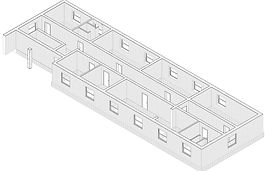

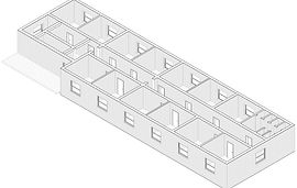
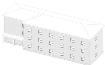
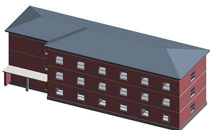
Creation of 3D model in Revit.
Top: axonometry for three levels. Bottom: Whole building axonometry.
Step 2
Creation of a generic family representing the opening
Driven by the planning requirements described earlier, a simple approach is to start from a generic family template, create an extrusion and apply the parameters for the opening entity as summarized in the picture below.
Note that the lintel component has been implemented as a nested family.


Completed family in Revit family environment showing the basic parameters
Final Drawing Representation
After placing every opening family at their designed locations and with their correct geometry, now it's time to create the final drawings through specific Revit presentation views.
The following picture shows drawings of typical wall elevation created in Revit with the use of the "opening family entity" as described above.
Depending on the drawing type and intent, this family is easily adapted in the aspect of geometrical configuration as well as in graphical presentation.

Drawing of masonry opening showing the existing situation and the proposed design.
Summary
As a conclusion, through simple steps and basic family creation commands and tools, it is possible to create a specific, custom made Revit family, which apart from helping in creating drawings and documentation, particularly helps to materialize the concept inside building model.
As an alternative, after this stage one can use other standard Revit commands such as wall profile command for further detailing of the 3d building model.